

Over on LinkedIn today there was a post with some generalizations about filters. The old “Active or Passive?” chestnut was raised. That reminded me of a post I wrote a long time ago, showing a microcontroller-based example where a passive filter - designed without the need for any software - beat active filter approaches into a cocked hat for the particular requirements of the customer. So here’s that golden (or is it enameled copper?) oldie one more time…
“Salmon taste on kipper money, that’s what you have!”, my Grandma used to say to me. I’m not sure it was true, since in those days I didn’t really like salmon. But she was making a Victorian point (yes, she was that old) that you needed to match up your expectations to your resources. Seems to me like the world could do with a bit more of that message today – but this isn’t a morality tale, it’s a filtering tale, so let’s move swiftly forward.
That phrase has become a talisman in my working life, every time someone wants the Earth from a signal path’s performance, but is only prepared to spend dirt to get it. I’ll wager that you know the problem too, either as someone who has been asked to deliver a seemingly impossible combination of performance and budget, or as someone who has asked for it.
Today’s story is about one of those cases, with a few details tweaked to protect the innocent (oh, and the customer...). The system needed some filters, there was a little bit of a spec from the customer, plus – much more useful – a good description of what the system was supposed to do. We’re talking bandpass filters with various center frequencies up in the ultrasonic region, where all but bats and old remote controls fear to tread. Signaling of various kinds happened at these frequencies, with reliable discrimination required for proper equipment operation.
The end equipment was of a type that’s manufactured in high volumes and installed in a wide range of environments, so that pointed straight away to the need for predictable performance over temperature and tolerance variations. And, needless to say, these things had to be cheap, so no chance of using any Unobtanium-grade components (a material, incidentally, that has been familiar to engineers for decades; what a pity James Cameron didn’t realize this).
The required selectivity implied four-pole filters with about 10% bandwidth (passband width about 10% of the center frequency). There is no shortage of ways to design this fairly basic spec as an active filter. There was just one little catch here though – the power budget. At least one of these filters is permanently on, and the maximum permissible system idle current, including the average current of all the associated digital clockwork, was down in the 30 uA region. Alarm bells rang straight away, as I saw in my mind’s eye the number of feasible op-amps on which I could build this filter count rapidly down to zero (in a John Connor, get-the-code-number kind of way). Low amplifier quiescent currents and high frequencies don’t mix, and the reason is simple. The lower the quiescent current, the lower the open-loop bandwidth of the amplifier. And the smaller the ratio of the open-loop bandwidth to the filter center frequency, the more trouble you are going to get into.
It’s only a rule of thumb, but it’s useful to look at the ‘f0*Q’ product when judging this, and relate it to the gain bandwidth product of the amplifier. Let’s say we were building a filter with a center frequency of 40kHz and a bandwidth of 10%, so a Q in the region of 10. The f0Q product would be 400 kHz (Q is dimensionless). Now divide this into the GBW of the amplifier to get a figure of merit. The rule of thumb is: if that ratio is less than ten, there may be trouble ahead. Meaning a 4 MHz GBW requirement in that instance.
Another processor vendor had already made an attempt to design a filter (actually, only a two-pole filter, so it wouldn’t have done the job properly), based around their fastest amplifier with suitably low quiescent current. The GBW of that amplifier was 350 kHz. My decades of experience as a Filter Wizard tell me that it is hopeless to expect predictable, stable performance from a filter that uses an amplifier that gives such a low GBW/f0Q figure of merit. While it’s possible to ‘pre-distort’ the component values so that one single example of the amplifier can deliver a frequency response that resembles the desired curve (at least in the passband), the variation in response over device batches, temperature and supply voltage means that reliable performance in production can simply not be achieved.
Maybe there’s a faster amplifier with low enough current drain? Well, the best I had seen at that time (the MAX9914, since you ask, with 1 MHz GBW on 20 uA rations) still leaves quite a filter design challenge – and actually, the customer really needed at least two amplifiers for a four-pole filter, and already we’d be way over our current budget.
Clearly, we needed a different approach. And salvation comes from the past, in the form of the venerable passive filter, using inductors as well as capacitors and resistors – but no amplifiers at all! The early proponents of active filters waged war on the passive filter, citing the cost, size and weight of the inductors as reasons why that noble circuit should be expunged from the canon of filter design, at least at sub-radio frequencies. But the inductor never went away and is still available for duty today in many forms.
But, you mutter, aren’t passive filters hard to design? Well, not doing it as I’m about to describe. The design approach I’ll use is the “narrowband capacitor-coupled” method, and it’s so easy that you can almost do it in your head. It certainly qualifies as what applications legend Dave Ritter called “Desert Island Design”, because no software at all is needed to get you pretty close to what you need. Let’s run through it step by step for one filter.
1 Impedance level, the customer wanted Zin>100 kOhm, so let’s say 200 kOhm if we want two filters permanently connected in parallel to the input signal. This is the source impedance and our reference impedance level.
2 A bandwidth of 10%, so let’s divide this 200 kOhm by 10 to get a required inductor impedance of 20 kOhm at the center frequency.
3 Let’s pick a center frequency of 30 kHz . we need an inductor of (20 kOhm divided by (2pi*30k) ) or ~0.1 Henrys. A quick search of the DigiKey catalog revealed the Bourns 70F range of standard 5% inductors (http://www.bourns.com/data/global/pdfs/70F_series.pdf ) from which the 70F101AF-RC looks good. Inherent quality factor is >>10 and self-resonant frequency is >>30 kHz, so it should suit our purposes.
4 Download the inductor data sheet and unpack the various parasitics – no inductor is perfect. Work out that the winding capacitance Cpar is 10.3 pF, from the self-resonant frequency of 157 kHz. The coil has a rated quality factor of 48 at 79 kHz, at which frequency its impedance will be 49637 ohms. If the only cause of the loss was the 287 ohm series resistance Rser you’d get a quality factor of 49637/287=173. So let’s add a shunt resistance that by itself would give us a quality factor of 1/(1/48-1/173) or 66.4. That resistance Rshunt will be 66.4*49637 , i.e. 3.29 Megohm.
5 Calculate the necessary capacitance to resonate a 0.1 H inductor at 30 kHz, and subtract Cpar. Comes to 271 pF. Now, take two of these tuned circuits, and couple them together with a capacitor equal to the resonating cap divided by the Q, or 28 pF. Knock off half of this capacitance from each of the tuning caps on the inductors, making them 257 pF each. The whole thing is shown in figure 1.
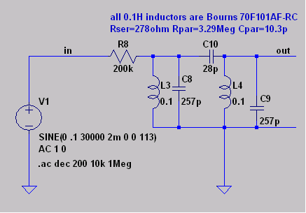
Figure 1: our hand-designed bandpass filter.
Let’s have a look at the frequency response, in figure 2. Pretty good, wouldn’t you say?
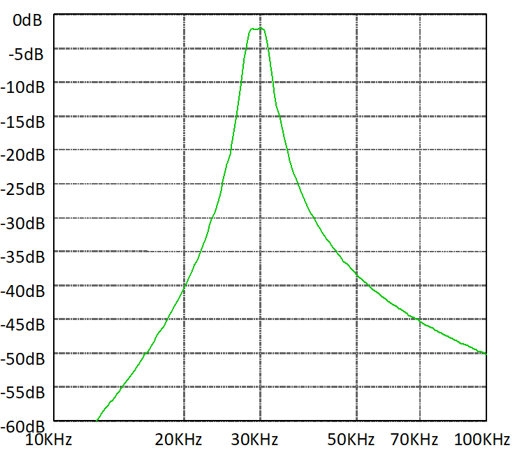
Figure 2: the frequency response of our hand-designed filter.
Now, I’ll admit that the inductors I chose are rather physically enormous in comparison to the tiny packages that we’re used to for inductors and capacitors these days. But the customer assured us that space wasn’t a problem. And the distributor’s small-quantity price for the inductors was a lot higher than you’d pay for a resistor or capacitor. But suitable coils could be sourced at far lower prices in mass production quantities. Further design optimization would permit a lower value of coil quality factor, further reducing size and cost.
Monte Carlo analysis in LTspice indicated that it is pretty resistant to component tolerances, and modern ferrite inductors are generally designed with quite low temperature coefficients of permeability. And don’t forget, this filter takes no DC supply current whatsoever! We just fed the output straight into a comparator input on the microcontroller, job done, power budget met, old-fashioned technology saves the day.
So – and I suppose this is a morality tale of sorts, after all – it pays not to recoil from (see what I did there?) the humble inductor, and what it can do for you when power budgets are tight!