


Specifying a crystal for use with the PCM1740 VCXO-DAC
Written in 2000, this really is from the way back machine

As you probably know, I worked for Burr-Brown and subsequently for Texas Instruments when B-B was acquired. I was responsible for their audio products in Europe; the PCM1740 was popular in systems where the audio master clock needed to be locally generated by a PLL. There seemed to be no good tutorial for my customers on how VCXOs (Voltage Controlled Crystal Oscillators) worked, how to spec the crystal, or how to select those mysterious capacitors to ground on either side of that crystal. So I wrote one. Here it is, lightly reformatted and spelling-tweaked. I don’t think you’ll find this on the TI website, although it’s still an active part. TI, you’re welcome.
The PCM1740 from Texas Instruments’ Burr-Brown division is a highly integrated, high quality audio digital-to-analog converter which includes circuitry for generating the clocks needed in digital broadcast video applications. Key to this circuitry is an integrated VCXO (voltage-controlled crystal oscillator). This is an oscillator whose nominal frequency is set by an external crystal but which can be "pulled" over a certain range, to allow synchronization with the broadcast video clock.
For any crystal oscillator design, the actual frequency of oscillation depends on the interaction between the crystal parameters and the oscillator circuitry. Crystals are supplied with a "rating plate" frequency value marked on the package, but this value applies only for one specific operating condition. Understand the way in which a "pullable" crystal oscillator functions, and the specification of the correct crystal parameters for the application becomes that much easier. Here we present a practical, first-principles analysis of the crystal oscillator which will be useful not only for the PCM1740 but for any similar project.
Why does a crystal oscillator oscillate?
It's the piezoelectric effect that makes a quartz crystal a much better resonator than a chunk of wood, rubber or even diamond. This effect allows an exchange between mechanical energy stored in the crystal's structure, and electrical energy stored in an electric field between two faces of the crystal. A small piece of quartz cut to exhibit a mechanical resonance at say 27 MHz can thus be turned into an electrical resonator. The resonator "looks like" a series resonant LC circuit, with a couple of extra parasitic components. Typical measured values for these are shown in figure 1. The values of the inductor and capacitor in the equivalent electrical circuit are so different from typical stray inductance and capacitance that the resonant frequency is almost completely (but fortunately not quite) unaffected by these external components. In addition, not much of the energy stored in the crystal gets lost as heat during each cycle of the mechanical oscillation, and the resultant resonant circuit has a huge 'Q' factor.

Figure 1 – the crystal

Figure 2 – impedance curve between 1 MHz and 100 MHz
Let's look at how the value of impedance of our crystal’s electrical circuit changes with frequency, in figure 2. Except very near a particular frequency, the crystal looks just like a small capacitor – as you'd expect, seeing as it is just a couple of metal connections with an insulator separating them. The magnitude of the impedance is falling at –6 dB per octave, and the phase shift is constant at –90o. Within a narrow frequency band, though, things really let rip; as the frequency is increased, first the impedance falls to a very low value, and them at a slightly higher frequency it rises to an extremely high one, before quickly returning to the curve expected from the small capacitance C2. Figure 3 shows this impedance curve “blown up” to show +/– 50 kHz from our chosen center frequency of 27 MHz. Note also that the vertical scale is in dB referred to 1ohm – i.e. 60 dB = 1kohm, and so on.

Figure 3 – crystal impedance between 26.95 MHz and 27.05 MHz
Either of these two extremes of impedance behaviour can be used to build frequency-dependent feedback around an amplifier circuit, and therefore an oscillator. In this case, we’re going to work at the frequency of the impedance peak of the crystal. We can move this peak to a lower frequency by adding extra capacitance across the crystal terminals – in figure 4, we sweep the added capacitance from zero up to 33 pF (the phase plot has been left off for improved clarity). Note that the impedance zero doesn’t move at all as the capacitance is swept – this is the native resonant frequency of the motional components of the crystal. The peak appears at our nominal frequency of 27.000 MHz when the added capacitance is 6.6 pF. The graph teaches us an important point – that the “frequency” of a crystal is not a constant, but depends on external factors such as the capacitance across the test fixture. Hold that thought!

Figure 4 – crystal impedance with a range of external loads from zero to 33 pF
The PCM1740 VCXO circuit
A complete oscillator tutorial is beyond the scope of this piece, so let's move straight to the type of oscillator circuit which will function well in the VCXO application we're trying to analyze and see why it works. The crystal is used in the feedback network round an inverting amplifier, together with a couple of variable capacitors to ground. This is convenient in integrated circuit design as it's possible to make an on-chip variable capacitor with one grounded terminal. There are some other ‘housekeeping’ components that have been included in the simulation for completeness. We’ve put in the same motional and stray parameters that we used in the impedance plots in the last section. The schematic shown in figure 5 is the input to the simulator and does not show the sustaining amplifier itself.

Figure 5 – wrapping some external components around the crystal
A plot of the gain of the feedback network, for a range of values of the variable capacitors (changed by the VCXO control voltage) taken from the actual PCM1740 oscillator, is shown in figure 6 (the vertical axis is linear gain). The feedback network is built around an inverting amplifier and the circuit oscillates at the frequency at which the phase shift goes through 180 degrees, turning the feedback into positive feedback.
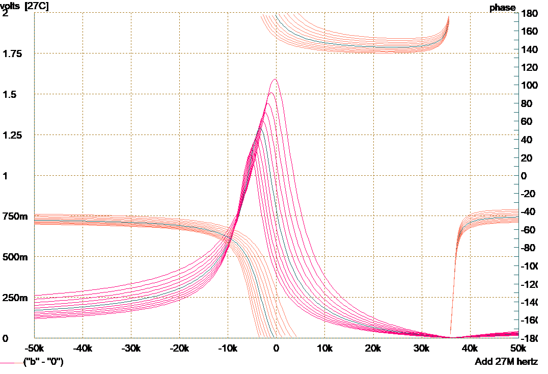
Figure 6 – the change of oscillator frequency (=180o phase point) with control voltage
The range of adjustment here is approximately +/–150 ppm, around the desired 27 MHz center frequency. Now of course that’s no coincidence, because we selected the measured motional parameters for the simulated crystal to ensure that this would happen. The question is, do we understand why adjusting the values of CV1 and CV2 over the given range actually causes the frequency of oscillation to shift by the amount it does? Let’s look a little more closely at what the crystal “sees” of the circuit connected around it. Ignoring all the biassing resistors, we can see that in fact the two capacitors CV1 and CV2 are connected across the crystal in series. So what we are doing is sweeping the “load capacitance” across the crystal from 4.8 pF to 9.3 pF. Figure 7 shows what effect this range of load capacitances have on the measured impedance. Aha! Exactly the same behaviour as the oscillator shows, with the nominal center frequency appearing with a load capacitance of around 6.6 pF – corresponding to 13.2 pF on each of CV1 and CV2.

Figure 7 – change in impedance for the actual range of load capacitance in PCM1740
A simple analysis of what’s going on leads us to a handy rule of thumb for estimating the motional capacitance specification for the crystal. The resonant frequency moves very slightly as the load capacitance is changed, because the total capacitance resonating with the effective inductance of the crystal is changed slightly. The motional capacitance Cmot is of the order of femtoFarads while the load capacitance Cload is in the picoFarad range. The fractional change in resonant frequency can be shown to be:

If we plug in the values we have, namely Cload = 9.64 pF (don’t forget the built-in 3.04 pF that the crystal has), ∆Cload = 4.5 pF (that’s how much we can vary the loading on the crystal), and ∆f/f = 300x10-6 (we want +/-150 ppm adjustability), we get a value for Cmot of 12.4 fF – strangely enough, quite close to the value which we have been using, which was a measured value from a real crystal. We see from this that if the motional capacitance is too small, a VCXO circuit may not be able to achieve the desired pullability.
This crystal clearly works in our circuit, but what do we ask the crystal manufacturer to make? Normal AT-cut crystals in the popular HC49/U low profile package are specified to operate with a specific "load capacitance" but this is often not the same as the value of the load capacitor we just so carefully determined. For instance, many vendors prefer to specify their crystals with a load capacitance of 15 pF. Fortunately, simulation can give us an easy answer to this question; we simply increase the added load capacitance from 6.6 pF to 15 pF; the frequency of the impedance peak falls to 26.992 MHz.
There is one more important parameter in the crystal specification that we have not covered in detail, and that is the motional resistance. This represents the lossiness of the crystal, and if it has too high a value, it is possible that the oscillator will not start up under all conditions. Oscillator startup is a big subject we can’t cover here, but the gist is that when the sustaining amplifier first ‘wakes up’ with increasing supply voltage, it will have quite a low gain. Increasing the series motional resistance of the crystal reduces the loop gain further, and if the oscillator doesn’t get kick-started by the initial disturbance of switch-on, it may not oscillate at all even once the supply voltage has come up fully. In the case of the PCM1740’s VCXO, this limiting series resistance has been determined to be at least 50 ohms, which is fortunately a lot higher than the values of typical crystals in this application.
Finally, then, we can write the specification of the crystal we need to get this VCXO running:
Resonant Frequency: parallel resonant at 27.000 MHz with an external load of 6.6 pF or parallel resonant at 26.992 MHz with an external load of 15 pF.
Motional Capacitance: Nominal 12 fF; not less than 10 fF.
Motional resistance: less than 50 ohms (expected typical 10 ohms).
Package / Structure Capacitance: typical 3 pF
Conclusions
The behaviour of crystals in practical modern oscillator circuits can be understood from their basic electrical equivalent circuit. The TI PCM1740 audio DAC, with built-in VCXO, serves to show how easy it is to define the crystal requirement exactly, even for critical close-tolerance applications.