
Why does the frequency response of my DAC droop?
A brief discussion of droop to support the next stack

Here’s an extract from an old piece on drooping DAC frequency responses. I’m stacking it first as supporting material for the next piece, a tale of operational amplifier woe from back in the 1980s that came to light in a filter designed to address the issue described below…
Have you ever experienced unexpected droop when you’ve plotted out the frequency response of a signal processing system? When you expected that the frequency response would be flat (or at least, accurate to the curve you designed to), but instead it rolls smoothly and lazily away from that target value, insulting you with its casual sogginess? If so, you’ve experienced the consequence of having a sinc() frequency response. You could say that you’ve had a clo-sinc-ounter – though possibly of a kind (or order…) other than the third. Let’s look at what I mean by that. This issue can crop up both at the input to, and the output, from a sampled data system. We’ll look at the output side here.
When you want to turn a stream of sample values back into an analogue signal, you apply those digital samples to a DAC. Now, most DAC ICs and modules have a ‘held’ output. That means that when they receive a new digital sample the output voltage changes promptly to the corresponding new value – and stays there, until the next sample comes along. This behavior is so commonplace that many engineers assume that it’s the norm and that the output voltage of such DACs somehow represents the sample stream correctly (apart from a bit of pesky high-frequency noise).
This is not true. This “hold” process causes the frequency response of such a system to differ from that of a system where the output voltage is only asserted very briefly at each sample instant. Such a spiky output voltage is hardly ever convenient in a real-world application, which is why you rarely encounter it.
Stretching each sample’s voltage out to “fill the space available” is an example of a zero‑order hold. The output frequency spectrum of such a system is equal to that of an ideal, spiky-output system multiplied by the spectrum of the rectangular impulse that fits between two sample points, i.e. has a width equal to the sample interval. Such a rectangular time response corresponds to a frequency response that has a sinc() characteristic. sinc(x) is shorthand for sin(x)/x, and there’s a Fourier looking-glass correspondence between rectangular in one domain and sinc() in another that crops up all over the place, not only in signal theory but in the whole of physics.
Calculating the value of the sinc function – the value of the argument x is pi times the ratio of signal frequency to sampling frequency – shows that the droop is already ‑3 dB at around 0.444 times Fs. Figure 1 shows the frequency effect of sinc() droop for a sample rate of 1 per second. Notice that it has deep but narrow notches at frequencies that are multiples of the sample rate.
Figure 2 shows a 0.444 Hz sinewave and the result of sampling it once per second. The peak value that is reached by a sample can clearly be the peak value of the input voltage. But as the sample clock ‘walks’ over the signal there are regions where the output voltage is low for an appreciable time.

Figure 1: The sinc() response of zero-order hold at 1 sample per second.
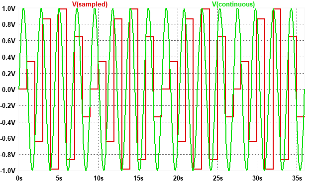
Figure 2: A 0.444Hz sinewave sampled – and held – at 1 sample per second.
Our 0.444 Hz signal is still present, but its level has been reduced, since some of the energy has been moved into higher frequency ‘images’, as shown in figure 3. You can see that the input signal’s single Fourier component peeps up 3 dB above the value of the 0.444 Hz component in the output signal.

Figure 3: Frequency spectra of the waveforms in figure 2.
The take-away is that the peak-to-peak value of a sampled sinewave is not a good measure of the energy contained at the fundamental frequency. As you increase the input frequency, progressively more and more energy in the output signal resides in those higher frequency image components instead – the muck that we usually try to filter out to get a nice clean output signal. Hence the droop.
Note that modern (sigma-delta) DACs designed for the audio market don’t exhibit this problem. That’s because they are not just updating once per sample and holding the signal. Deep in the bowels of the converter they are running much faster, and then applying digital filter techniques to produce an output that magically does not appear to have been sampled at all on casual inspection. The fact that it’s so easy to get an audio DAC with a super-flat frequency response also makes it easy for engineers to forget that “old school” sampling DACs don’t inherently have this flat response property.
That’s the “why” for the output part of our system. Can the input path also cause droop that might be detectable when we analyze the data in the digital domain without even going back to analogue? Well, yes, sometimes it can – and I’ll cover that in a future piece -- K